
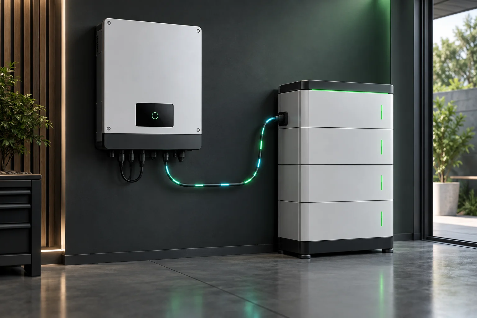
No. A CAN or RS485 port does not, by itself, guarantee that a battery and a hybrid inverter are compatible. The physical interface is only one part of the connection. The battery voltage window, charge and discharge current, communication protocol, firmware, cable pinout, configuration and documented test status must also match.
This distinction matters because two products can both be labelled “48V” and both have CAN or RS485 terminals, yet still be unsuitable for closed-loop operation together. A safe compatibility review starts with the exact battery and inverter models—not just their nominal voltage or connector names.
Port, protocol and compatibility are different things
A communication port describes the electrical interface available on the equipment. A protocol defines how the connected devices exchange data. Compatibility means the complete system can operate within the electrical and communication limits documented for both products.
| Item | What it tells you | What it does not prove |
|---|---|---|
| CAN or RS485 port | A communication interface is physically available. | That both devices use the same messages, baud rate, addressing or cable pinout. |
| 24V or 48V label | The nominal battery platform. | That the real charge, discharge and startup voltage windows overlap. |
| Lithium battery setting | The inverter may offer a lithium operating mode. | That a particular battery brand, model, BMS or firmware revision is supported. |
| Successful power connection | DC voltage may be present at the inverter terminals. | That closed-loop limits, alarms, state of charge and shutdown commands are being exchanged correctly. |
In other words, the connector is the doorway. It does not tell you whether the two devices speak the same language or follow the same operating rules.
What must match before connecting the battery?
1. Battery voltage and operating window
Start with the complete DC voltage ranges in the current manuals. Compare the battery’s minimum and maximum operating voltage, charging limits and protection thresholds with the inverter’s permitted battery range and startup requirements.
Do not confuse a PV input voltage with a battery voltage. They belong to different DC circuits. Likewise, a nominal 48V label is not a substitute for the actual operating window. Current ELECNO low-voltage products use model-specific 24V or 48V battery platforms, and the exact limits must be confirmed on the selected model page and current documentation.
2. Continuous and peak current
Check the maximum charge and discharge current on both sides. The permitted system value cannot exceed the lowest applicable limit among the inverter, battery, BMS, protection devices, conductors and connection hardware.
This is especially important in low-voltage systems, where higher power can require substantial battery current. An inverter power rating alone cannot establish the required battery configuration. Battery quantity, parallel rules, cable sizing and overcurrent protection need a project-specific electrical design.
3. Communication protocol
CAN and RS485 are interface families, not universal battery languages. Confirm that the exact inverter firmware supports the protocol used by the exact battery BMS. The review should cover the manufacturer-specified communication mode, message set, baud rate, addressing and any required master/slave arrangement.
A generic statement such as “supports CAN” is insufficient. If the available documentation does not identify a supported protocol or approved integration path, treat compatibility as unconfirmed.
4. Cable and pinout
Two devices can use the same plug shape but assign different functions to its pins. Before energizing the system, verify the cable part number or wiring diagram specified for the exact equipment combination. Confirm CAN-H/CAN-L or RS485-A/RS485-B assignments, signal ground requirements and termination guidance.
Do not copy a pinout from another model or make assumptions from cable colour. Incorrect communication wiring may prevent data exchange and can expose interfaces to unintended voltage.
5. Firmware and configuration
Compatibility can depend on the inverter firmware, battery BMS firmware and selected battery protocol in the commissioning menu. Record the versions before installation and confirm whether an update, a specific communication profile or a model-specific setting is required.
After configuration, verify that the inverter reads plausible battery information rather than assuming that the absence of an immediate fault proves correct operation.
6. Documented support and test scope
The strongest evidence is current documentation that names the relevant models, versions and conditions. A compatibility list, integration guide or written project confirmation should be checked for its date and scope. A test involving one battery model or firmware revision should not automatically be extended to an entire brand.
ELECNO does not treat a shared nominal voltage or communication port as proof of compatibility. When requesting a review, provide the exact model identifiers and available technical documents so that known values and missing evidence can be separated.
Closed-loop communication versus open-loop operation
In closed-loop operation, the BMS and inverter exchange information such as state of charge, allowable charge current, allowable discharge current, alarms and protection states. The inverter can then respond to limits communicated by the battery—provided the integration is supported and configured correctly.
Some systems may offer an open-loop or voltage-based operating method. That does not remove the need for engineering checks. Charge settings, low-voltage cut-off, current limits and battery protection still need to follow the battery manufacturer’s requirements. Do not use open-loop settings as an improvised workaround for an unsupported communication pairing.
Practical rule: if closed-loop compatibility cannot be documented, do not assume that selecting manual voltage settings creates an approved or equivalent integration.
A six-step compatibility review
- Identify the exact products. Record the complete inverter model, battery model, BMS model and hardware revision.
- Compare electrical limits. Check battery voltage, startup voltage, charge/discharge current and permitted battery configuration.
- Confirm the protocol. Verify the supported CAN or RS485 communication profile for both devices.
- Confirm the physical connection. Use the specified cable and pinout; review termination and grounding requirements.
- Check versions and settings. Record firmware versions and apply only documented protocol and battery settings.
- Commission and verify. Confirm valid battery data, current limits, alarms, charge/discharge response and safe shutdown behaviour under the approved commissioning procedure.
Installation and commissioning should be completed by qualified personnel using the current manuals, applicable electrical rules and the protection specified for the project.
Information to send for an ELECNO compatibility check
A useful request includes enough detail to identify both the electrical platform and the communication path:
- installation country, grid voltage, frequency and phase;
- exact ELECNO inverter model under consideration;
- battery brand, exact model, quantity and nominal voltage;
- battery operating window and maximum charge/discharge current;
- BMS model, CAN/RS485 protocol information and firmware version;
- available battery datasheet, manual, compatibility list or wiring diagram;
- PV array, backup loads and largest starting load;
- required documents and project schedule.
You can review the ELECNO battery and BMS planning overview, compare the current low-voltage hybrid inverter range, or submit a model-specific compatibility inquiry.
Frequently asked questions
Does a 48V lithium battery work with every 48V hybrid inverter?
No. Nominal voltage is only a starting classification. The operating voltage window, current limits, BMS protocol, firmware, cable pinout and documented support must also match.
Can I use RS485 if CAN communication does not work?
Only when both product manuals document a compatible RS485 integration for the exact models and versions. Changing the interface does not solve a protocol, firmware or pinout mismatch by itself.
Does seeing battery state of charge prove full compatibility?
Not necessarily. Commissioning should also verify allowable current values, alarms, charge/discharge response and protective behaviour under the supported procedure.
What is the first document needed for a compatibility review?
Start with the current datasheets and installation or communication manuals for the exact inverter and battery models. Include firmware information and any model-specific compatibility record available from the suppliers.
This article provides planning guidance, not an installation wiring diagram or a declaration that any unnamed battery is compatible. Final selection, protection, wiring and commissioning must follow current model documentation and local requirements.