Low voltage hybrid inverters, matched by more than voltage.
The current residential range connects to nominal 24V or 48V battery platforms. A safe match also depends on charge and discharge limits, interface, protocol, firmware and system protection.
AC domain1Φ / Split / 3Φgrid format varies by market and model
Quick answer
A low-voltage hybrid inverter uses a nominal 24V or 48V battery platform. The battery voltage is separate from the PV input voltage and AC output. For this documented range, 24V appears on two 3.6kW single-phase models; the remaining listed models use 48V.
Platform comparison
24V for the compact end. 48V for the wider range.
Voltage alone does not size a system. Use this overview to choose the right branch, then verify the complete model datasheet and installation design.
01 · compact platform24V
Two documented 3.6kW single-phase models for EU and US electrical platforms.
EUELE SPI2436V120-5003.6kW · 120A charge · 500V PV Voc max
Ranges summarize the July 2026 neutral brochure selection tables. They are not universal limits for every model inside a platform.
Power and current
Lower voltage means current matters sooner.
For the same power transfer, a lower battery voltage generally requires higher DC current. That affects conductor sizing, terminals, protection, heat and allowable cable length.
Concept onlyCurrent ≈ Power ÷ Voltage
Real design must also account for efficiency, battery operating window, surge, temperature, cable route and applicable standards.
01
Use the operating window
Do not design from the nominal 24V or 48V label alone. Confirm minimum, rated and maximum battery voltage.
02
Check both current directions
Battery charging and inverter discharge can have different model limits and protection requirements.
03
Size the complete DC path
Review cable, fuse or breaker, disconnect, busbar, terminal and enclosure temperature as one path.
04
Confirm parallel architecture
Parallel inverter operation does not automatically prove a battery bus or BMS can support the combined current.
Representative models
Move from platform to model.
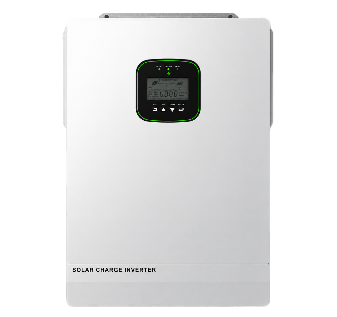
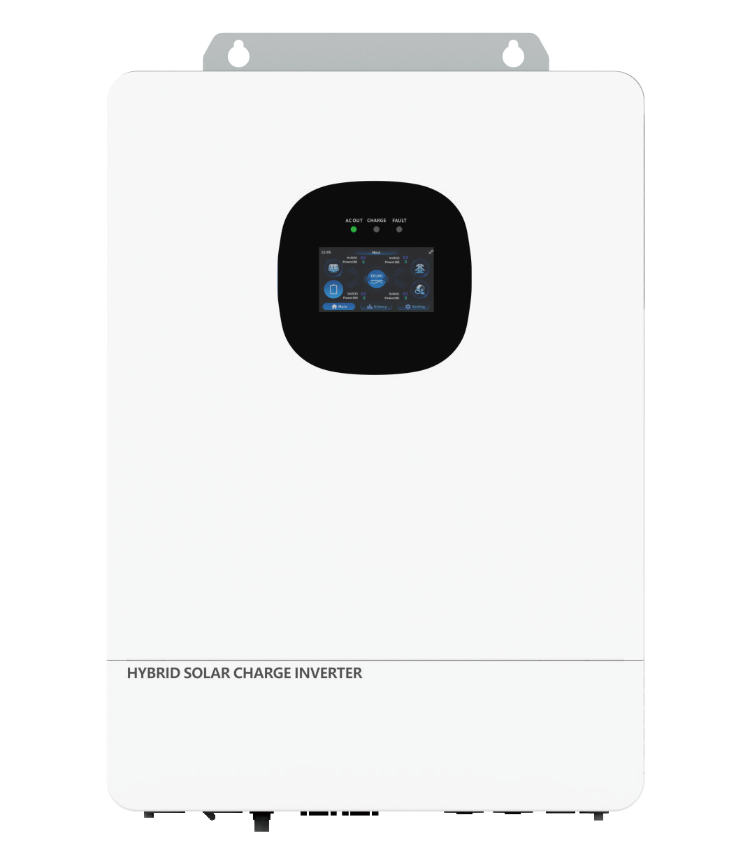
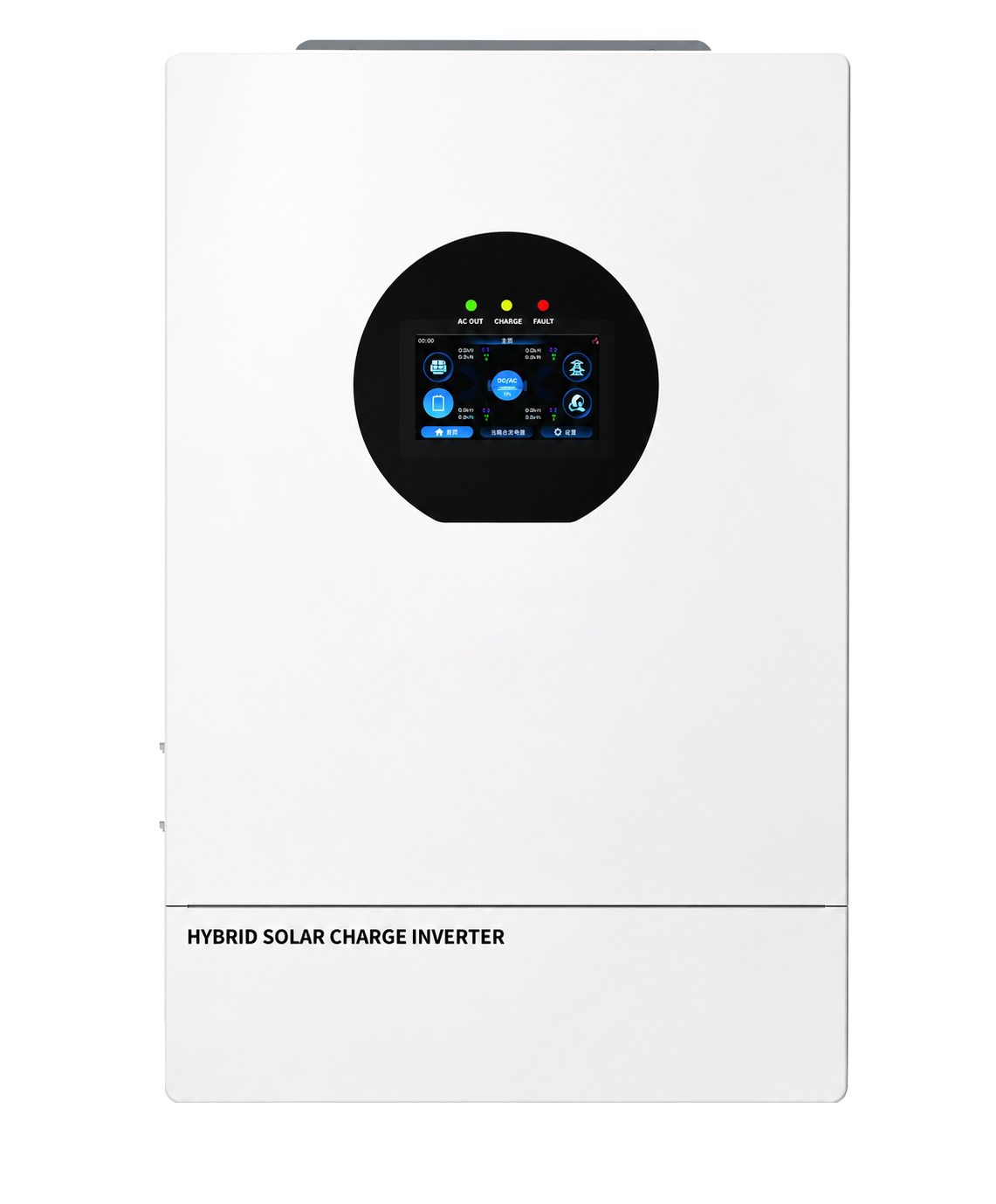
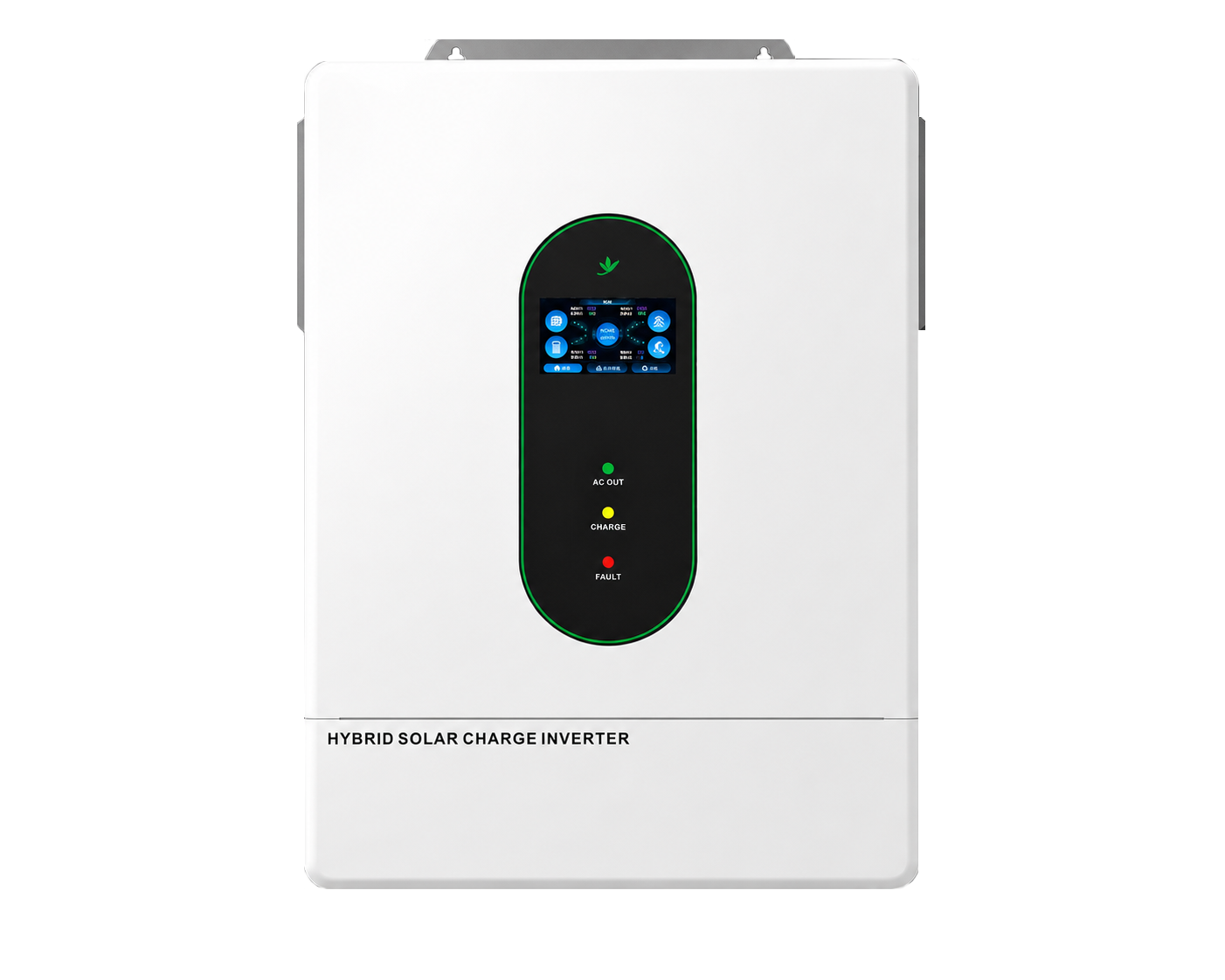
These four documented models illustrate the range. Product images are representative family visuals until exact model-image mapping is confirmed.
Battery minimum, rated, maximum and charge voltage must fit the exact inverter model.
ElectricalGate 02
Current capability
Check BMS limits, battery configuration and inverter charge/discharge requirements.
ElectricalGate 03
Physical interface
Confirm CAN or RS485 port, cable pinout, grounding and termination.
InterfaceGate 04
Protocol and firmware
A shared connector does not prove compatible commands, addressing or software revision.
DigitalGate 05
Fault behavior
Confirm alarms, charge limits, shutdown sequence and recovery behavior.
System
Voltage boundary
Do not confuse three different voltage domains.
Domain
What it describes
Documented values
Selection question
Battery voltage
DC battery platform connected to the inverter
24V / 48V nominal
Does the full operating window and current capability match?
PV voltage
Solar-array DC input before conversion
300V / 500V / 1000V maximum Voc by model
Is cold-weather string Voc below the model limit?
AC voltage
Grid and load-side electrical service
Depends on EU/US model and phase format
Does the model match the actual grid connection?
The 1000V figure in the current range belongs to the PV input of a documented EU three-phase model; it is not the battery voltage.
Low-voltage FAQ
Confirm the platform before the product.
These answers define the current documented scope. Model-specific data and local electrical requirements remain controlling.
On this site, it means a hybrid inverter designed around a nominal 24V or 48V battery platform. It can still have a much higher PV input voltage, because PV and battery are separate DC domains.
No. The right platform depends on power, current, battery configuration, protection, cost and system architecture. The current 24V models occupy the compact 3.6kW end; the 48V range covers more output and phase options.
No. The physical port is only one layer. Protocol, cable pinout, addressing, firmware and supported fault behavior must also match.
Only after checking the inverter parallel design, total DC current, battery BMS capability, protection and manufacturer-approved architecture. Parallel-capable inverters do not automatically approve every shared battery arrangement.
The current residential inverter brochure supplied for this website documents 24V and 48V battery platforms only. A high-voltage battery inverter page will remain unpublished until matching product documentation is supplied.
Compatibility inquiry
Send the exact battery, not just “48V.”
Include battery model, series/parallel configuration, voltage window, current limits, BMS interface, protocol version and target inverter model.
With your permission, we use Google Analytics to understand page visits and inquiry-button use. We do not send your form answers to analytics. You can change your choice using Analytics preferences in the footer. Privacy policy