
Confirm 230/400Vac service
The listed AC connection is L1+L2+L3+N+PE at 50/60Hz.
Check grid and neutral rulesEU series · three-phase residential inverter
Documented for 3L/N/PE 230/400Vac systems with a 48V battery platform, two 36A MPPT channels, generator input and support for one to six parallel units.
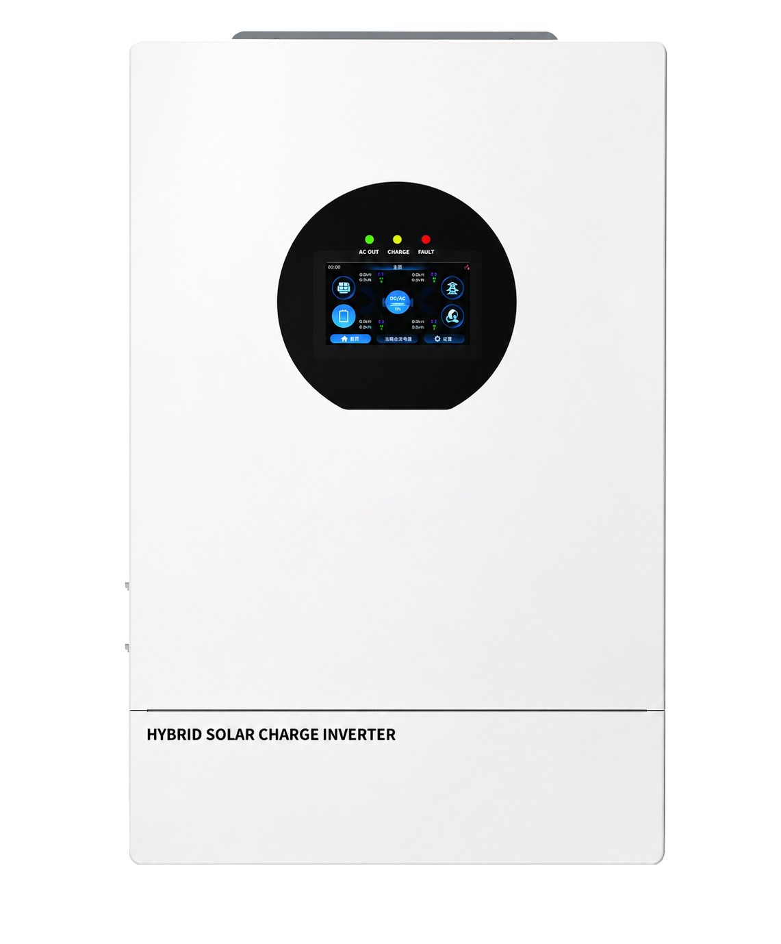
Family visual · confirm image and current document revision for the exact supplied unit
Selection answer
The model fits an EU-style 230/400Vac three-phase branch where 16kW rated output, two high-voltage PV trackers, generator input and parallel expansion are relevant. It should not be selected from output power alone.
The listed AC connection is L1+L2+L3+N+PE at 50/60Hz.
Check grid and neutral rulesThe brochure lists up to 300A charge and 340A discharge current.
Verify BMS and conductorsMaximum DC input is listed as 16000W + 16000W with 1000V maximum.
Confirm MPPT current revisionGenerator input and one to six parallel units are documented, but the complete architecture must be confirmed.
Use current model documentsDocumented operating paths
The brochure lists AC coupling, independent three-phase CT anti-backflow, generator input and battery-less operation. Final protection, metering, phase loading and control logic require the current manual.
160-1000V input range
2 × 36A MPPT table value
PV → inverter
02 / Energy conversion
ELE TPE48160V300-1000P
32000VA peak for 5s
Family visual · exact unit may vary300A max charge
340A max discharge
Battery ↔ inverter
230/400Vac three-phase
10ms typical transfer
AC source connection
Functional overview, not an installation wiring diagram. Follow the model-specific manual for terminal assignments and protection.
Model specification
Values below are transcribed from the supplied July 2026 neutral brochure. Confirm the current datasheet revision before PV string design, battery engineering, generator integration, parallel planning or installation.
Brochure-listed functions
These functions are listed on the supplied model page. Availability, firmware behavior, accessories, protection coordination and configuration should be checked against the current supplied package.
Check project compatibility →The brochure also lists AC coupling. Confirm CT quantity, orientation, metering arrangement and commissioning method.
Both are brochure-listed values. Verify the actual phase load schedule, surge duration and permitted operating conditions.
The table lists three-phase generator input, dry-contact control and a typical 10ms generator-to-inverter transfer time.
The expansion range is documented; unit grouping, shared battery current, protection and communication layout require engineering review.
The special-functions row lists these functions. Confirm hardware, firmware, regional behavior and applicable documentation.
Before specification
The model combines up to 1000V PV input with a 48V battery platform. Every conductor, protective device and interface must be selected for its own voltage and current path.
Calculate cold-weather Voc, operating voltage and channel current against both MPPT inputs.
Confirm the 40-60Vdc window, 300A/340A current path, protocol, firmware and cable pinout.
Document per-phase continuous and surge loads, neutral current and acceptable imbalance.
Confirm source switching, unit count, master logic, protection, CTs, wiring and communications.
Request the current datasheet, manual and applicable certificate scope for the target market.
The brochure specification table references CE (IEC 62109-1, -2), IEC 61000 and C2. The same page has an MPPT-current wording conflict: its specification table states 36A + 36A while a feature bullet states 32A per channel. Request the applicable certificate, exact model scope and current technical revision before relying on either compliance or string-design claims.
Model FAQ
The supplied model page controls the answers below. Project suitability still depends on the complete PV, battery, three-phase, generator and parallel design.
No. It is the maximum PV-side DC input voltage. The battery platform is nominal 48V with a listed 40-60Vdc range.
The table lists 16000W rated output at 3L/N/PE 230/400Vac, with an L1+L2+L3+N+PE connection and 32000VA peak power for 5 seconds.
The quick selection guide and specification table list 36A per channel. A feature bullet says 32A, so request the current model revision before final string design.
The brochure lists one to six units. The actual unit grouping, shared battery, protection, CT, wiring and communication arrangement must follow the current manual.
Send the destination country, model, PV strings, battery, three-phase load schedule, generator requirements, planned unit count and required documents through the inquiry form.
Model-specific inquiry
Send the country, PV strings, battery model, phase load schedule, generator plan, parallel count, quantity and documents required. The inquiry form will prefill this model number.
Request ELE TPE48160V300-1000P data →With your permission, we use Google Analytics to understand page visits and inquiry-button use. We do not send your form answers to analytics. You can change your choice using Analytics preferences in the footer. Privacy policy