
Confirm 120Vac service
Rated output is single-phase L+N+PE at 50/60Hz.
Do not treat it as split phaseUS series · dual-MPPT 120Vac inverter
Documented for 120Vac single-phase systems with a 48V battery platform, 9kW dual-MPPT PV input, a 300V PV ceiling and support for one to six parallel units.
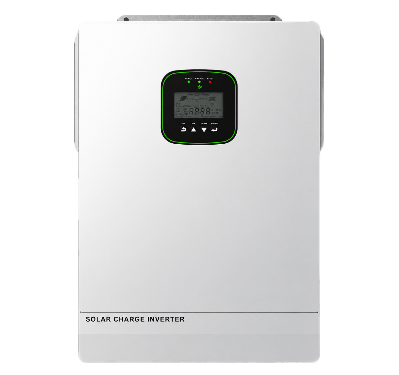
Family visual · confirm image and current document revision for the exact supplied unit
Selection answer
The model fits a documented 120Vac single-phase branch where two PV trackers, 6.5kW rated output and parallel expansion are relevant. Its 150A PV charging figure must not be confused with the 120A battery charge limit.
Rated output is single-phase L+N+PE at 50/60Hz.
Do not treat it as split phasePV charging is listed at 150A; battery charge/discharge is 120A/153A.
Use the correct design fieldMaximum input is 4500W per channel with 22A per tracker.
Keep cold-weather Voc below 300VOne to six units are listed, but grouping, protection and communications must be confirmed.
Use current model documentsDocumented operating paths
The brochure lists on-grid, off-grid and battery-less operation. Final PV strings, battery current, 120Vac service, protection, parallel arrangement and operating modes must follow current documentation.
90-300V input range
2 × 22A MPPT
PV → inverter
02 / Energy conversion
ELE SPI4865M150-300P
9750VA peak for 5s
Family visual · exact unit may vary120A max charge
153A max discharge
Battery ↔ inverter
120Vac single-phase
10ms typical transfer
Grid input · load output
Functional overview, not an installation wiring diagram. Follow the model-specific manual for terminal assignments and protection.
Model specification
Values below are transcribed from the supplied July 2026 neutral brochure. Confirm the latest model revision before PV design, battery integration, parallel planning or installation.
Brochure-listed functions
These functions are listed on the supplied model page. Availability, firmware behavior, parallel accessories and configuration should be checked against the current supplied package.
Check project compatibility →PV open-circuit voltage must remain below 300V and operating voltage inside the 90-260V MPPT range.
The values come from different specification rows. Battery, BMS and conductors must be designed to the applicable battery-side limit.
The exact table value is used here. Verify the starting profile of motors and other critical loads.
The brochure mentions grouping up to 39kW. Exact topology, phase arrangement, protection and accessories require current documentation.
Dry-contact generator control and PV plus grid direct supply are listed; confirm project behavior before design.
Before specification
PV charging, AC charging and battery charge/discharge values describe different limits. Use the correct table row for each conductor, BMS, protection device and operating mode.
Assign modules across both MPPTs and calculate cold-weather Voc and operating current.
Confirm model, 40-60Vdc window, 120A/153A current, protocol, firmware and cable pinout.
Confirm country, single-phase service, frequency, neutral, earthing and grid requirements.
Confirm unit count, phase grouping, master logic, protection, wiring and communication accessories.
Request the current datasheet, manual and applicable certificate scope for the target market.
The brochure specification table references UL 1741, CSA C22.2 No. 107.1 and FCC Part 15 Class B. This website does not present those references as independently verified certificates. Request the applicable certificate, exact model scope and revision before relying on a compliance claim.
Model FAQ
The supplied model page controls the answers below. Project suitability still depends on the complete AC, PV, battery and parallel design.
The table lists 150A as maximum PV charging current. Battery maximum charge/discharge is separately listed as 120A/153A.
The brochure lists two MPPT channels with 4500W maximum DC input and 22A maximum MPPT current per channel.
The brochure lists one to six units. The actual grouping, protection, phase arrangement, wiring and communications must follow the current manual.
The table lists 6500W rated output at 120Vac single-phase and 9750VA peak power for 5 seconds.
Send the destination country, AC service, PV strings, battery, planned parallel arrangement and required documents through the inquiry form.
Model-specific inquiry
Send the country, AC service, PV strings, battery model, loads, planned parallel count, quantity and documents required. The inquiry form will prefill this model number.
Request ELE SPI4865M150-300P data →With your permission, we use Google Analytics to understand page visits and inquiry-button use. We do not send your form answers to analytics. You can change your choice using Analytics preferences in the footer. Privacy policy